Our team Chemical Device
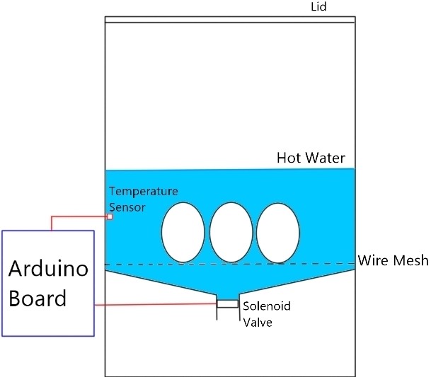
We came out with an idea to help automate the cooking of soft-boiled eggs.
It will help solve the eggs being overcooked, as the eggs are very delicate to heat. We have decided to implement a way to remove the hot water from the egg to stop the cooking process from the heat present.
Team Planning, allocation, and execution
In my team, we consist of Chief Executive Officer: Bjorn, Chief Strategy Officer: Vernon, Chief Operating Officer: Nigel, Chief Financial Officer: Roy.
Here is our finalized BOM:

Here is our initial Gantt chart:
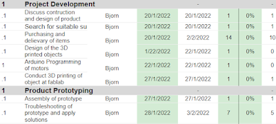
In the end, we did not follow the plan due to sudden changes such as the omicron variant. Hence we had to change our schedule:

Design and Build Process
Design of CAD for 3D printed parts:
https://cp5070-2021-2b02-group3-bjorn.blogspot.com/2022/02/project-development.html
 | ||
CAD of Valve Disk
|
For the designing and printing of parts, we had to design and print 2 parts for our prototype, valve connection, and disk, 2 of each.
For the valve disk, I created a circle of diameter 50mm, drew 2 smaller circles of diameter 7.6mm and a small rectangle in the middle of dimensions 3.6mm x 5.2mm. Lastly, I extruded the sketch by 5mm.
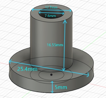
For the valve connects I drew a larger circle with a diameter of 25.4mm, a middle circle of 12.7mm, and a small circle of 7.6mm. I extruded the outer circle by 5mm, the middle circle by 21.55mm, and left the small circle not extruded.
I designed the middle hole of the valve disk to be the same as the stem of the stepper motor so it fits snugly onto the stepper motor. Since the tube we purchased had an internal diameter of 12.7mm we also designed the outer diameter of the valve connections to be 12.7mm to fit the tube. The holes of the disk were designed to have a sufficient flow rate when water is being drained. The thickness and height of the disk and valve connection were chosen to have a smaller form factor for our valve mechanism.
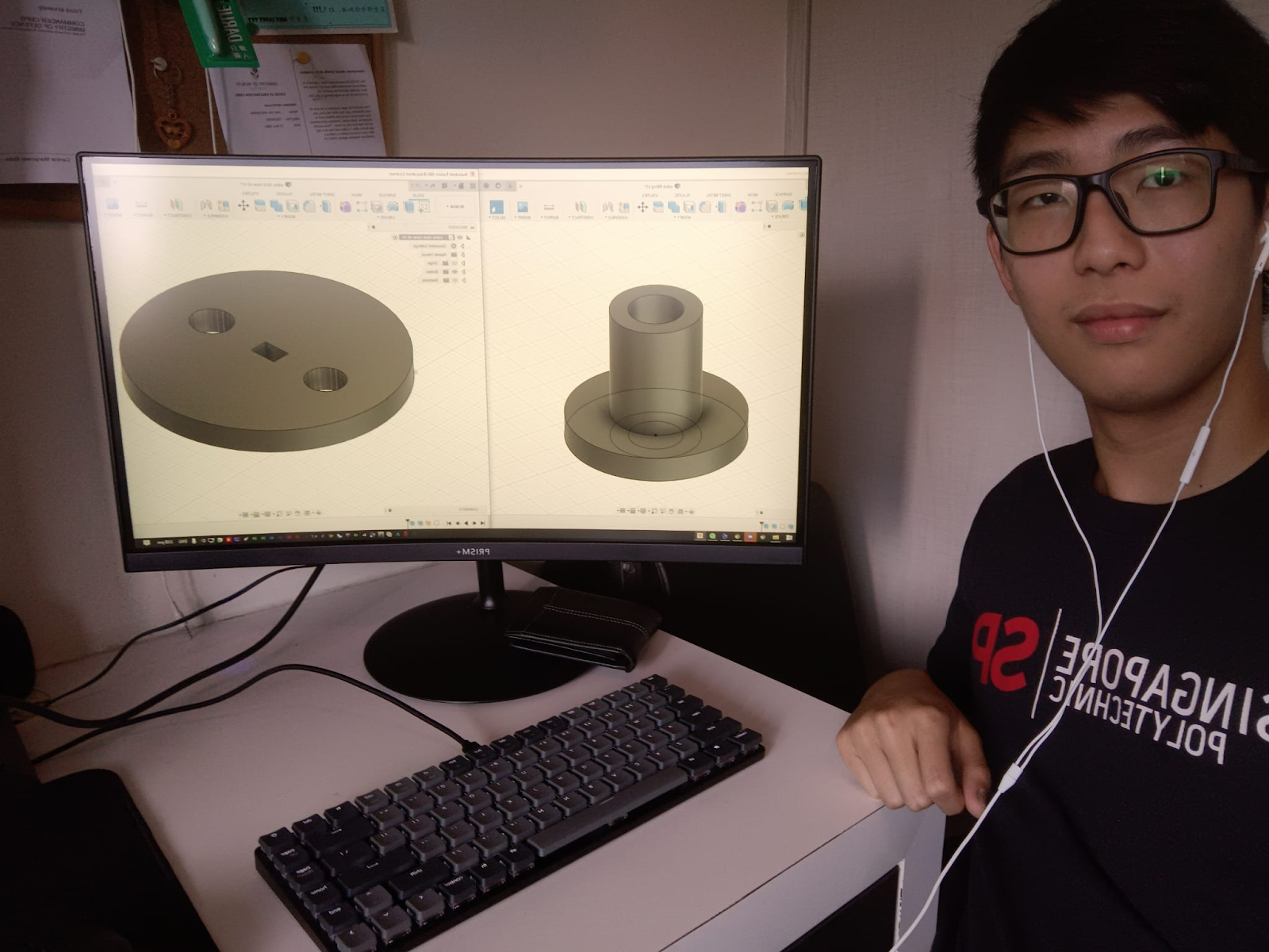 |
| Hero Shot of CAD |
Programming Arduino(Nigel).
https://cp5070-2021-2b02-group3-nigel.blogspot.com/2022/02/project-development.html
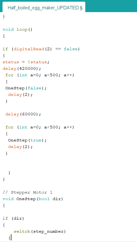
We wanted the stepper motor to be able to have a 7 mins delay before turning 90 degrees for 1 min and then turning back to a close position. This will be run when the button on the board is pressed. In order to start, I had to copy and paste the code from the seller's website as it contains the code which allows the motor to move. Then in the void loop, I start off with the Toggle Button code in my Arduino Practical blog (DC Motor part) since I will be using it to run the code. Then I added a delay for 7mins (420000ms). The stepper motor has 2048 steps per revolution so, in order for it to turn around 90 degrees, I added them for a loop. Initial a (number of steps) = 0, a will keep on adding until it reaches 500 steps (90 degrees). Now I have to add the delay for every step and the direction. The minimum delay I found on the website is 2ms per step so I add a delay of 2ms in the for a loop. OneStep(false) is the direction of the step which is defined by the initial code. Currently, it is turning in a clockwise direction. For that, we wanted it to stay at this position for 1 min in order for all the hot water to drain out, and hence we added another delay for 1 min (60000ms). Lastly, we wanted the motor to turn back to its original position, so I copy the first for loop and paste it at the bottom, and changed the direction to anti-clockwise, OneStep(true) to OneStep(false).
Here is what the code looks like:
File for the code: https://drive.google.com/file/d/15UW6aG8j52MsCDbGREOLuV5RaiDPSKtf/view?usp=sharing
Brainstorming for the prototype(done by me).
For the assembly process, from what Bjorn designed and Nigel coded, my main task that I spent the most time on was to get the prototype working as well as come out with new ideas when the old failed.
Initially, we were following a different design:

However, due to issues we faced, we had to drop this idea completely. So the team and I started brainstorming. I came out with the idea to try to implement a vacuum and to perhaps use a tap as a start-stop valve.

But the final idea that we implemented was thought of by Vernon. I did a sketch after the idea has been selected and tried to visualize the design:

We spent the next day in school to try to implement the design, such as fabricating the initial tube, mounting of motor, and testing the mechanism:
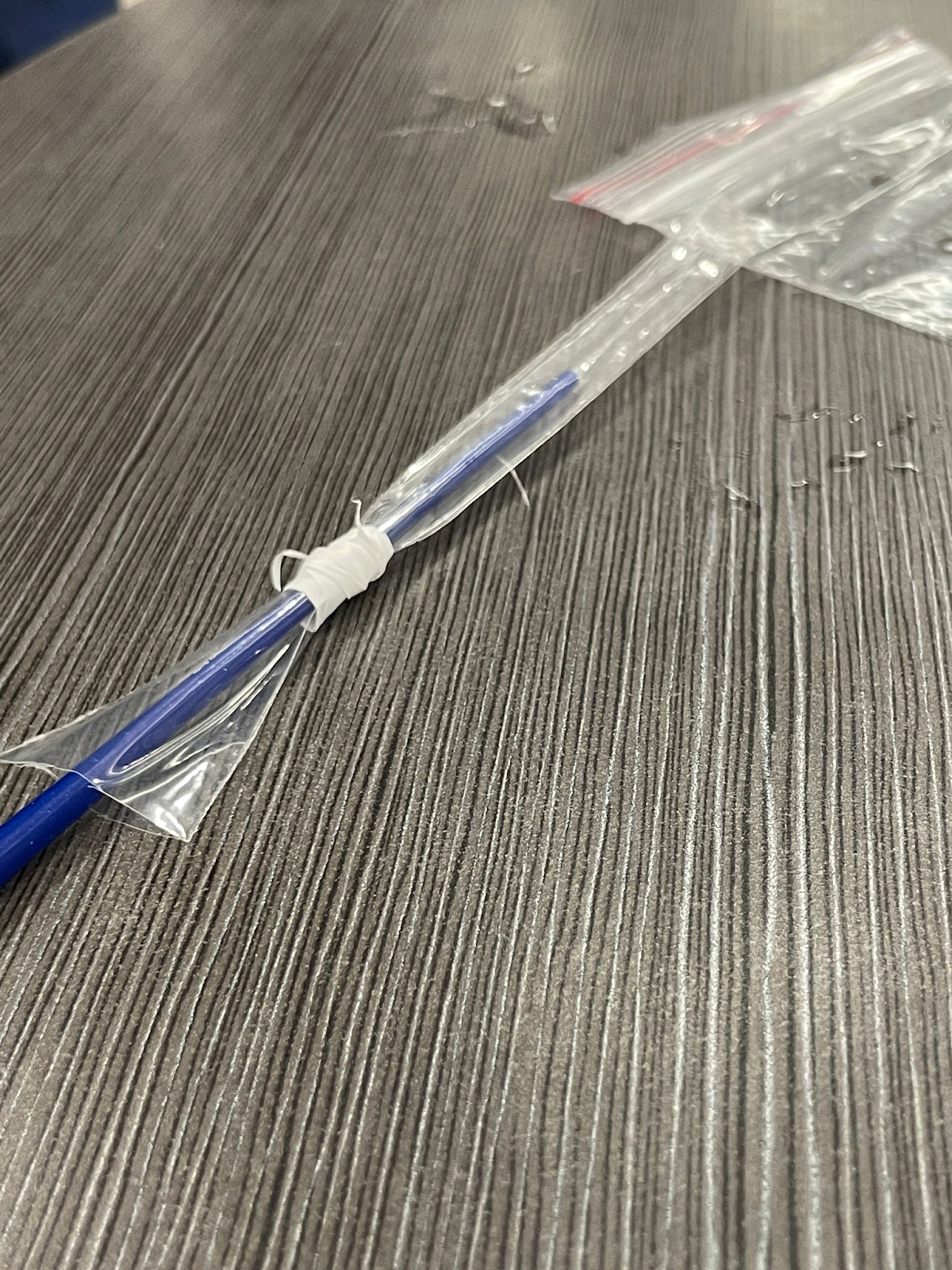
However, the tube we fabricated was proven to not be durable enough, hence in the end we used a straw instead, which meant that we had to rebuild the entire prototype by dismantling it.
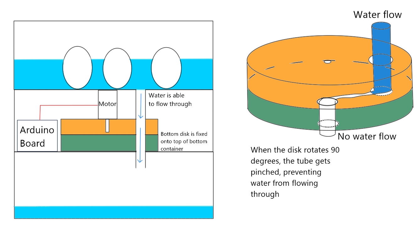
Valve Mechnism Schemetic

3D printing of Parts (Done by Vernon)


In the end, we are glad that we completed our prototype:

Problems and solutions
After we got our prototype to work, we left it overnight. However, the next day, the stepper motor rusted badly due to the water leakages we suffered in the days before. Luckily, we had a second stepper motor which we were able to switch to.
When faced with water leakage problems in our initial prototype, we added sealant between the potential gaps, however, the added resistance proved too hard for the stepper motors to turn. Hence we had to brainstorm new ideas on the spot(view above).
And initially, we wanted to use a 12v solenoid valve, however, we had to change that idea and design a valve mechanism ourselves.
Project Design Files as downloadable files https://drive.google.com/drive/folders/1cXuNUvqClMpqXbsQs_gDCVzex5HCwjKA?usp=sharing